Smart Sliding Gate Opener Control Board AC110V/220V Supports 433mhz Rolling Code Remotes, Limit Switch & Safety Beam Compatible


Smart Sliding Gate Opener Control Board AC110V/220V Supports 433mhz Rolling Code Remotes, Limit Switch & Safety Beam Compatible
Please note
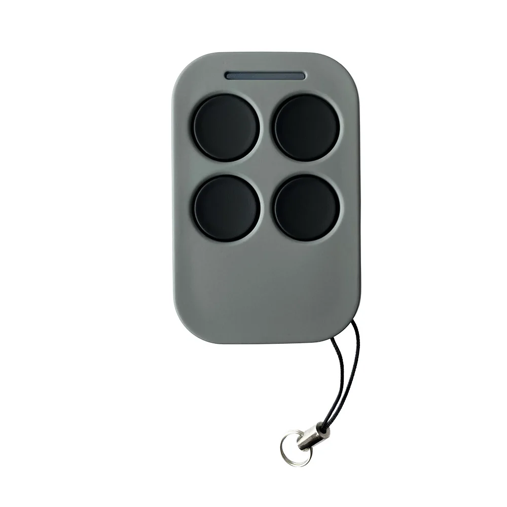
This remote control is exclusively designed for use with our products. The control board is only compatible with the remote model shown in the product images and will not work with other remote controls.
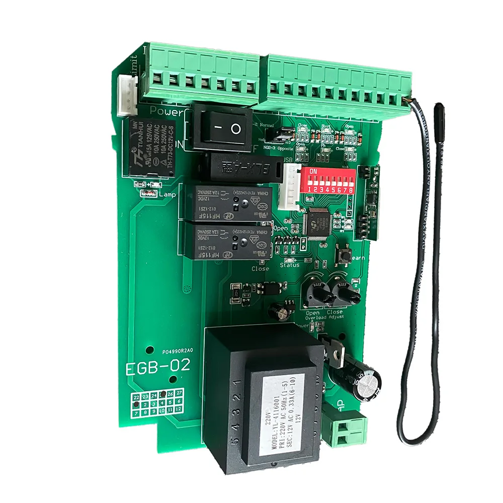
220/110V AC Sliding Gate Opener Control Board
The is a high-performance smart control board designed for AC-powered sliding gate openers. It supports Giant customized rolling code remotes (up to 100 units), integrates flexible input/output terminals, and offers a variety of configuration options to meet both residential and commercial automation needs.
Key Features:
AC Power Input: Compatible with AC 110V/220V ±10% voltage.
Motor Compatibility: Designed for sliding gate motors with customizable forward/reverse wiring depending on motor installation (left/right side).
Remote Control Support: Learns up to 100 remotes (Giant rolling code); supports single-button or multi-button mode.
Photocell Safety Beam Input: For obstacle detection to prevent injury or property damage.
Limit Switch Integration: Supports both NC and NO modes to detect gate fully opened/closed positions.
Auto-Close Timer: Adjustable auto-close times (10s, 30s, 60s) via DIP switches.
Pedestrian Mode: Remotely open gate partially (6s) for pedestrian access.
Condominium Mode: Prevents gate opening while it's already in motion.
Built-in Overcurrent Protection: Separate settings for open and close thresholds to prevent motor strain.
DC 12V Output: Auxiliary power output (max 200mA) for external sensors or access devices.
USB Firmware Upgrade Support: Compatible with EG-USB module for software upgrades.
Note:
1. You must use our U disk module (EG-USB).
2. The USB flash drive used for the first time needs to be formatted as FAT32.
After the upgrade, the original RF pairing data and menu setting data are still there.
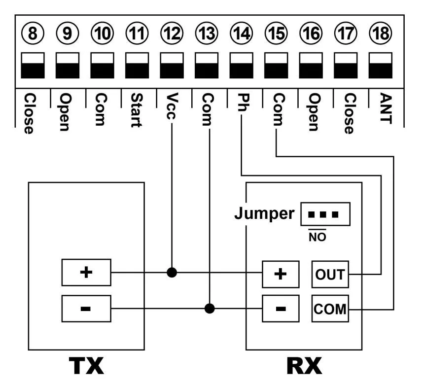
Connect with safety beam
Connect terminal ⑮ with the “COM“ of photocell RX.
Connect terminal ⑭ with the “OUT “ of photocell RX.
Connect terminal ⑫ with the “+ “ of photocell RX and TX.
Connect terminal ⑬ with the “- “ of photocell RX and TX.
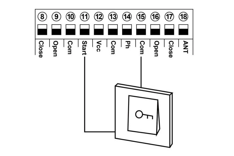
Connect with start terminal
Start terminal is used for connecting with some external devices , such push button, swipe card, wired keypad, receiver etc.
Control gate by “ open-stop-close-stop-open ” mode
Terminal ⑪ and ⑮ are for connecting with the push button.
Note! If you connect the swipe card or wired keypad, etc devices, please also connect with ⑫Vcc and ⑬Com to get the power supply.
Connect with open gate device (Loop detector, swipe card, etc)
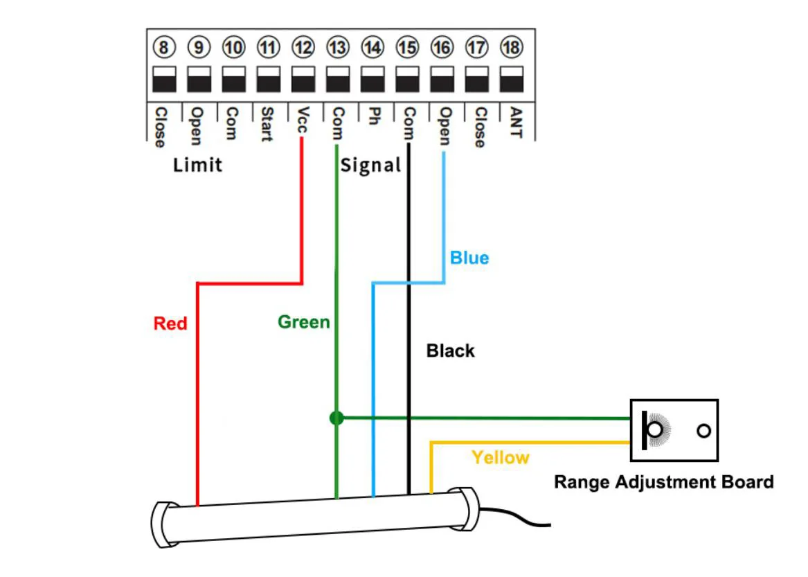
Loop detector wire information:
Definition of the 5 –core cable:
RED →Input Voltage (+)
GREEN →Ground/Common (-)
BLACK →Relay’s Common
BLUE →Relay’s Normally Open
YELLOW →Range adjustment potentiometer (POT)
Loop detector wire diagram:
Red wire: connect with terminal ⑫.
Green wire: connect with terminal ⑬ and range adjustment board.
Black wire: connect with terminal ⑮.
Blue wire: connect with terminal ⑯.
Yellow wire: connect with range adjustment potentiometer.
Function testing
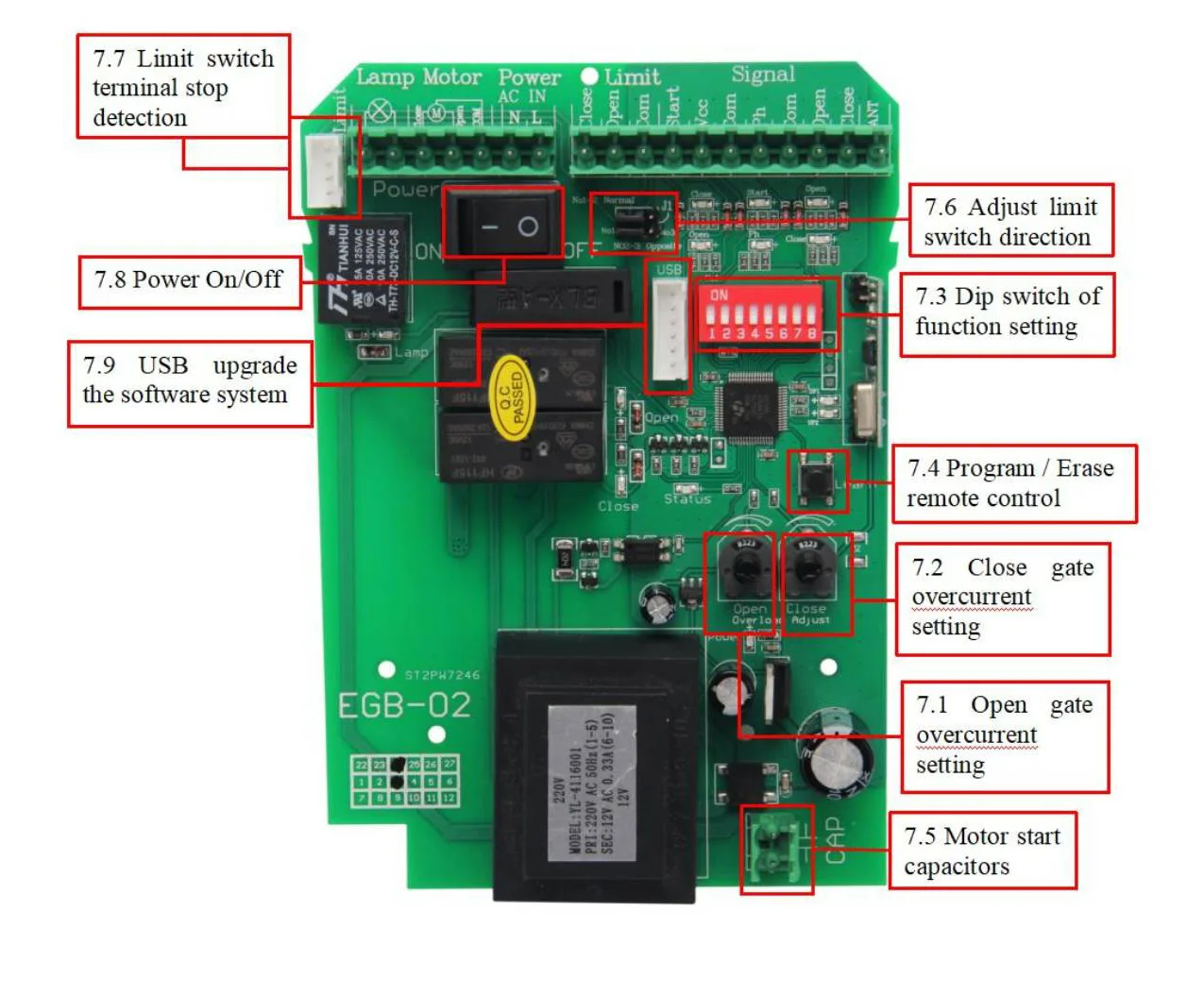
Function setting by dip switch
Dial-up 1: Limit mode optional
OFF: NC mode(Factory setting)
ON : NO mode
Limit switch for opening and closing gate direction setting(J1):
Normal :Short circuit cap simultaneously No1 and No2 of J1 (Factory setting)
If the motor system install in the left of the gate. Please adjust the J1, short the cap simultaneously No2 and No3.
Dial-up 2: Safety beam mode
OFF: NO mode(Factory setting)
ON: NC mode
Please don’t remove the copper wire, if you don’t install the safety beam, it will cause the gate can not be closed.
If the gate connects with a safety beam, please remove the copper wire from the safety beam terminal in the control board.
While it meet obstacles during closing, it will stop and rebound to open. After the gate move to the open position, after 2 seconds the gate will auto close again if the obstacle signal disappear. If not , it will not auto close until the obstacle signal disappear.
Dial-up 3 &4: Auto close time setting
Auto close function activated after gate complete open to its place and stop by limit switch.
Dial-up 3 &4, OFF-OFF: Auto close function disabled(Factory setting)
Dial-up 3 &4, ON-OFF: 10S
Dial-up 3 &4, OFF-ON: 30S
Dial-up 3 &4, ON-ON: 60S
Dial-up 5&6: Auto-closing timer for swipe card terminal triggering
When remote control triggers the pedestrian mode (remote control button 2 or 4), the gate will stop after open 6s. If auto close function activated, the gate will auto close after gate open to 6s. Auto close time setting as follows:
Dial-up 5 &6, OFF-OFF: Auto close function disabled(Factory setting)
Dial-up 5 &6, ON-OFF: 5S
Dial-up 5 &6 , OFF-ON: 10S
Dial-up 5 &6 , ON-ON: 30S
Note:
1.When the motor is running, the motor will stop immediately if triggers pedestrian mode
2.After triggering the pedestrian mode to open the gate for 6s, no mater it enter the countdown to close the gate or stop status, If trigger again, the gate will close the gate immediately.
Dial-up 7: Condominium mode setting
OFF:Condominium mode disabled(factory setting)
ON: Condominium mode activated
When the gate is opening, trigger remote control and the start interface are invalid until the door is opened.
When the gate is closing, trigger remote control and the start interface , the gate will stop to close and auto open until the opening limit is reached (the remote control and the start interface are invalid when the gate is opening).
Dial-up 8: Remote control buttons mode
OFF: Single button control circularly
First button control gate open,stop, close, second button use for pedestrian mode
ON: Three buttons control
First button control gate open,second button control gate close,third button control gate stop, fourth button use for pedestrian mode
Not:Please choose the remote control mode firstly before remote control code clearing to control board
Program and erase remote control
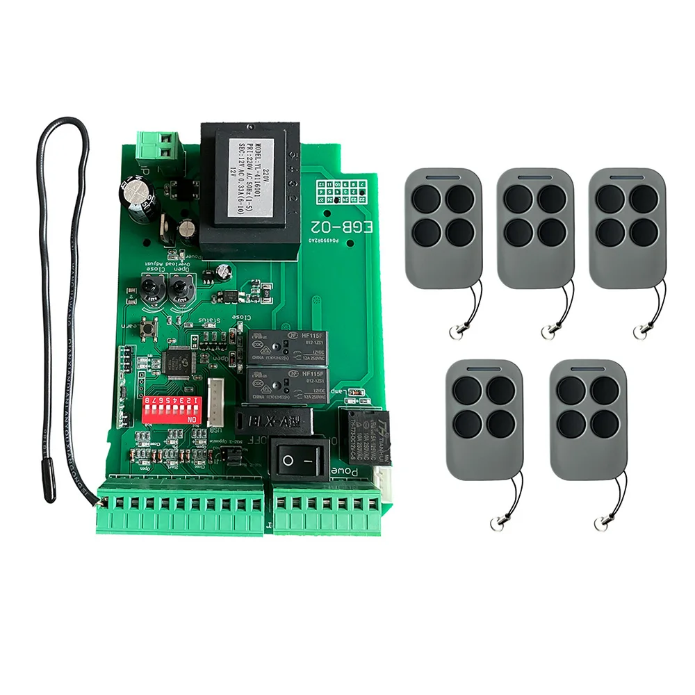
The control board can memory more than 100 pcs remote control.
● Program the remote: Press the learn button for at least 1 second and then release, the LED indicator will light on. Now user needs to press the button on the remote control, with the learn button indicator LED flash twice, which means the code learning is successful.
After the user presses the learn button, within 6 seconds, if the controller doesn’t receive the signal from the remote, the controller’s LED indicator will turn out and exit the code learning statute.
● Erase the remote: Press and hold the learning button for 6 seconds, while the learn button indicator LED light on and flash twice, release the button. Now all remotes can not control the gate.
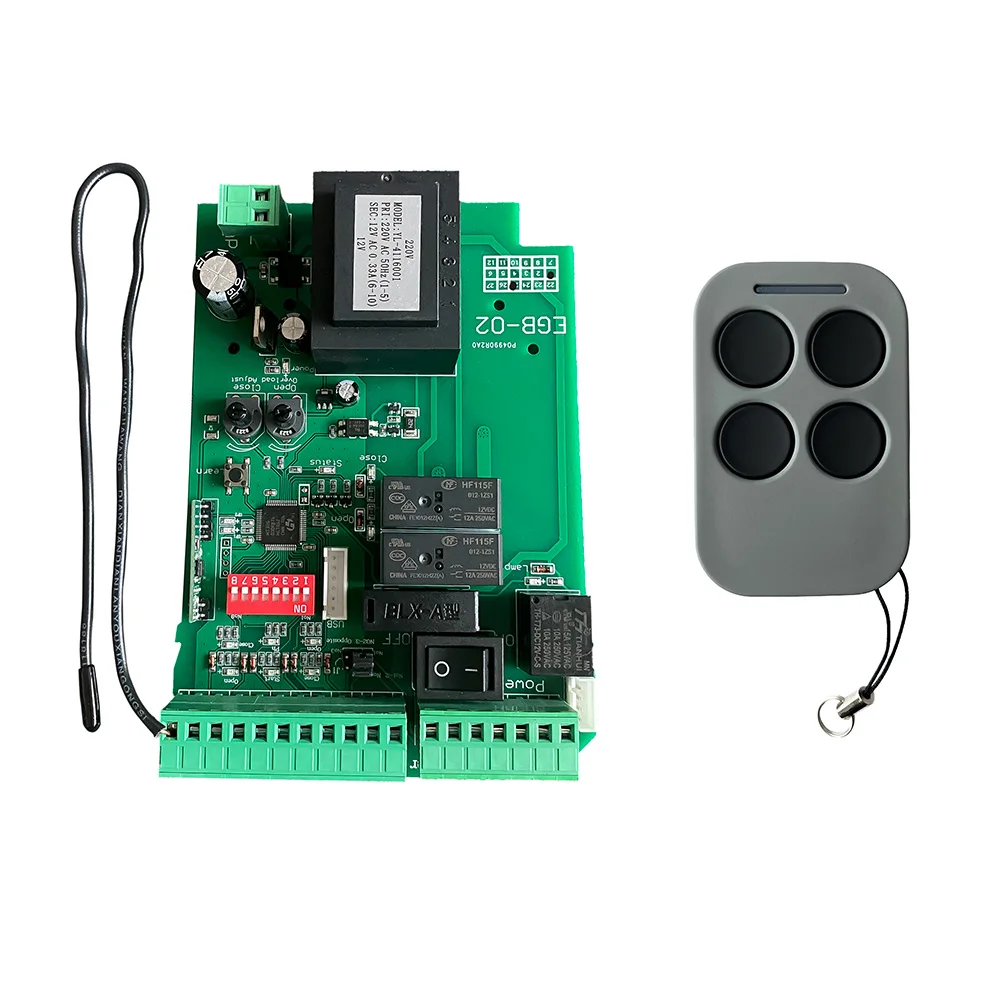
Package Includes
1 x control board,
1 x wiring diagram (instruction manual),
How to operate your gate opener
Each remote has 4 buttons, there are two remote control modes for optional. The factory setting is a single-button control mode. If you want to change to use the three-button control mode, please reference the data set of dip switch 8.
Single button control mode:the 1st remote button is used to control the gate as “open-stop-close-stop”, the 2nd button is used to control the PED mode.
Then if needed, the 3rd and 4th button can be programmed into another gate opener controller, same function as the 1st and 2nd button.
Three-button control mode: remote 1st button to control gate open, 2nd button to control gate close, 3rd button to control gate stop. 4th button to control gate PED mode.