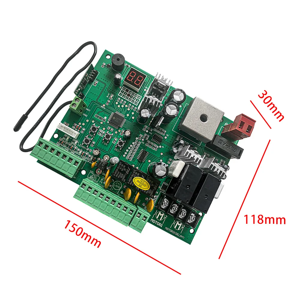
AC 24V PCB Control Board For Electric Gate Swing Gate Auto Gate Door Opener 433.92mhz Rolling Code Remote Control


AC 24V PCB Control Board For Electric Gate Swing Gate Auto Gate Door Opener 433.92mhz Rolling Code Remote Control
Specifications:
1. Material: High-quality PCB Board
2. Power supply: AC 24V, Available for adding 24V backup battery.
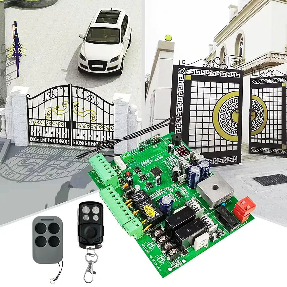
3. Application: Used for double or single DC 12-24V gate opener.
4. Encoder For transmitter: 433.92mhz rolling code.
5. Allowed Transmitters Quantity: Up to 120PCS.
6. Speed -adjustable function.
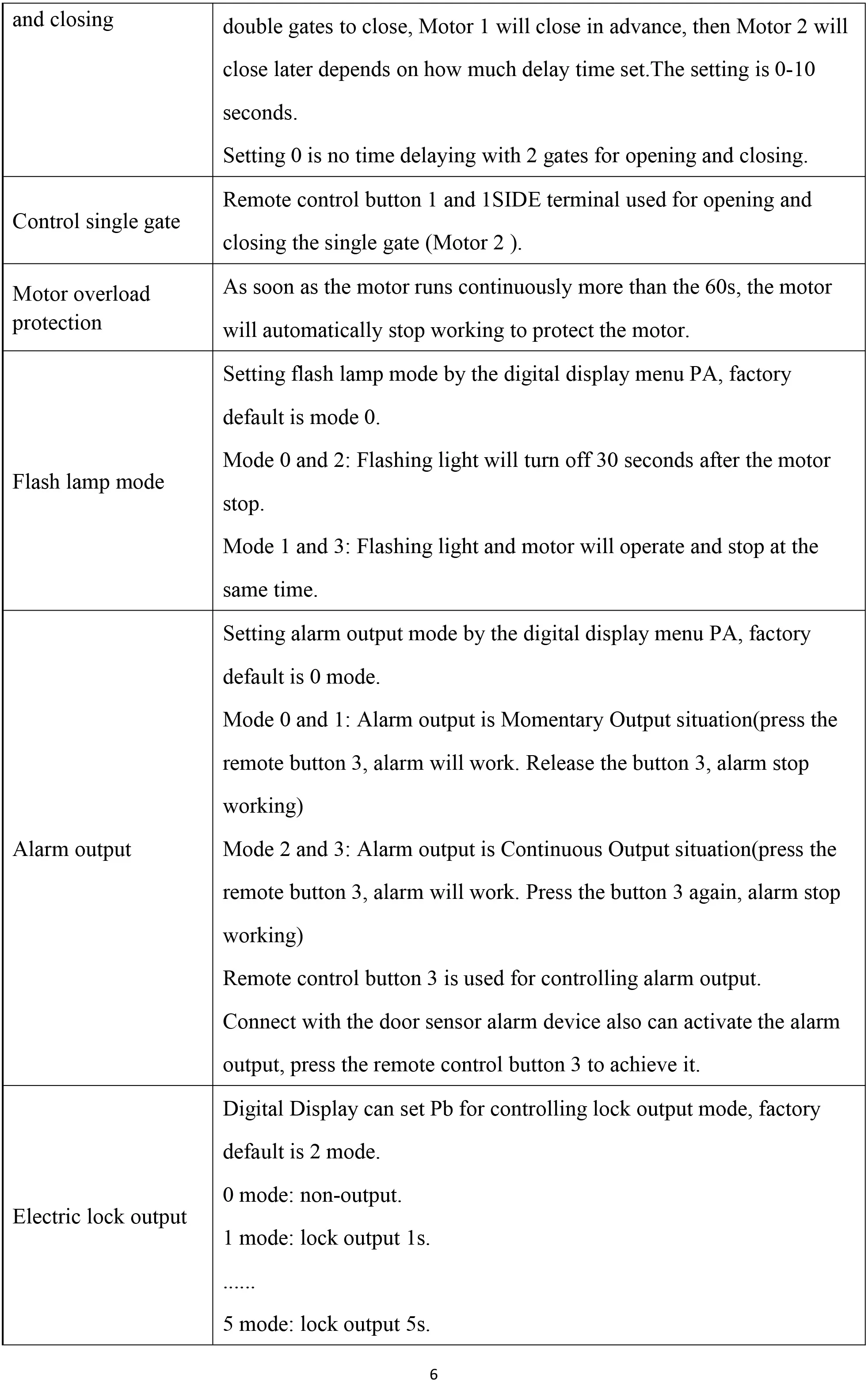
7. Auto closing/opening,opening/closing delay time adjustment.
8. Adjustable Residence sensitivity.
9.Terminals available for loop detector, photocell, push button, keypad, access control equipment
10. Digital LED Menu brings a easy setting, plug and play.
11. Open/Close single leaf or double leaves.
12. Total 60's working time to protect the motors.
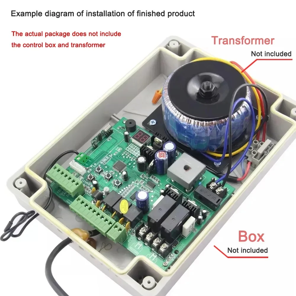
Please note
This control board can only work with our remote control, it cannot work with other remote controls
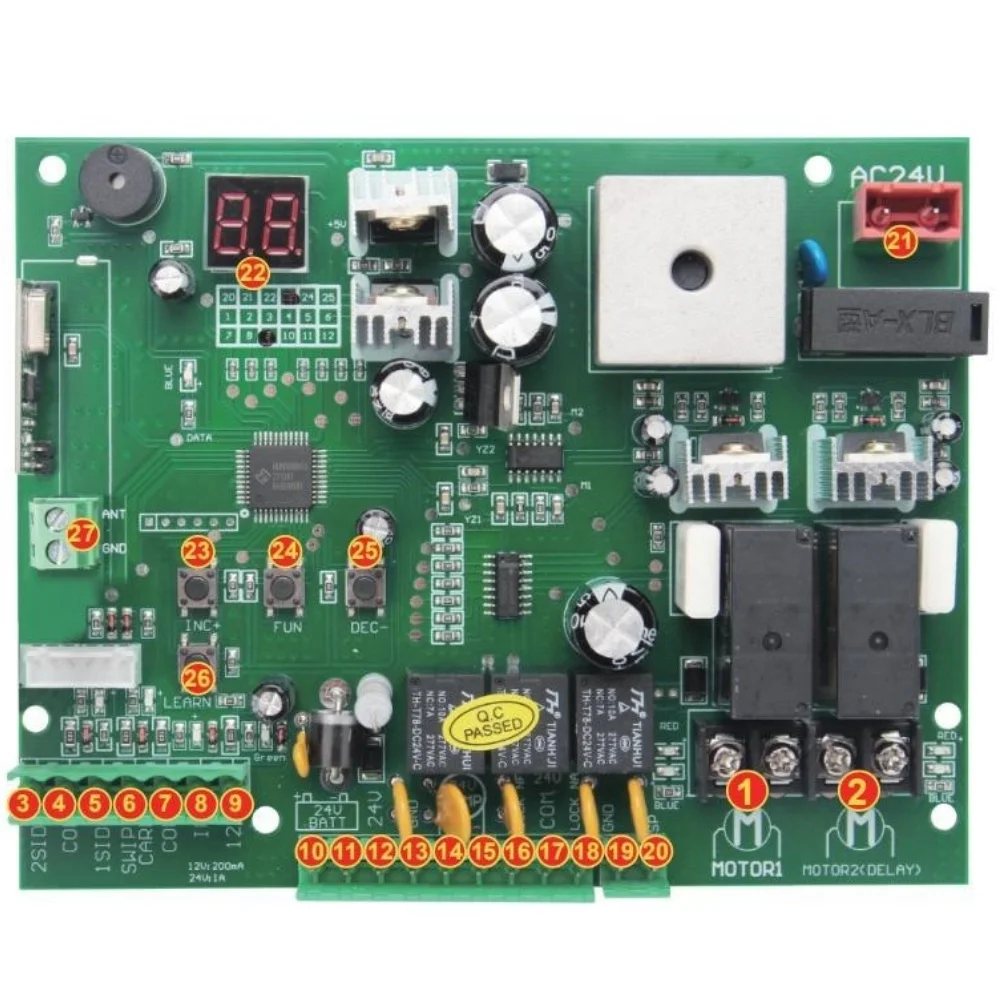
Control panel number corresponding function
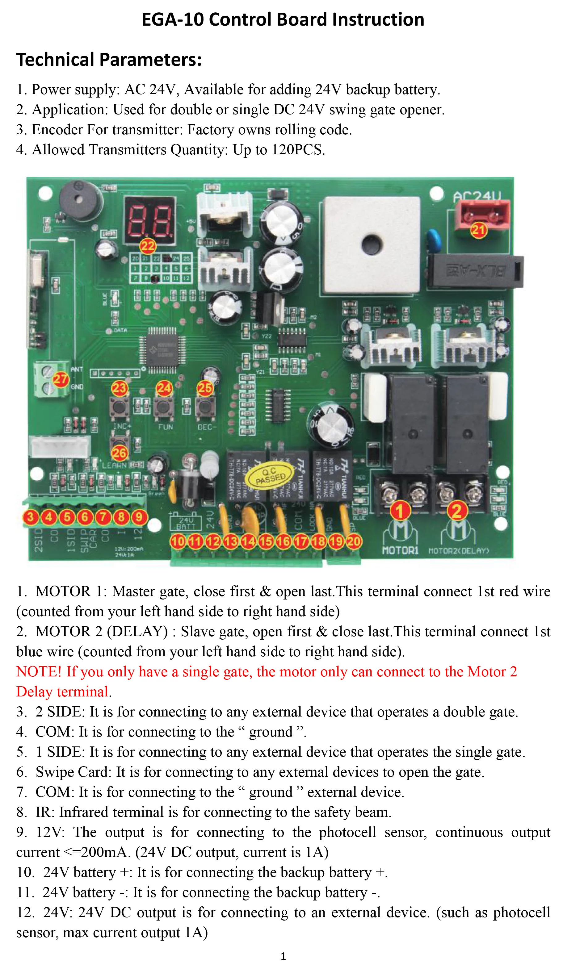
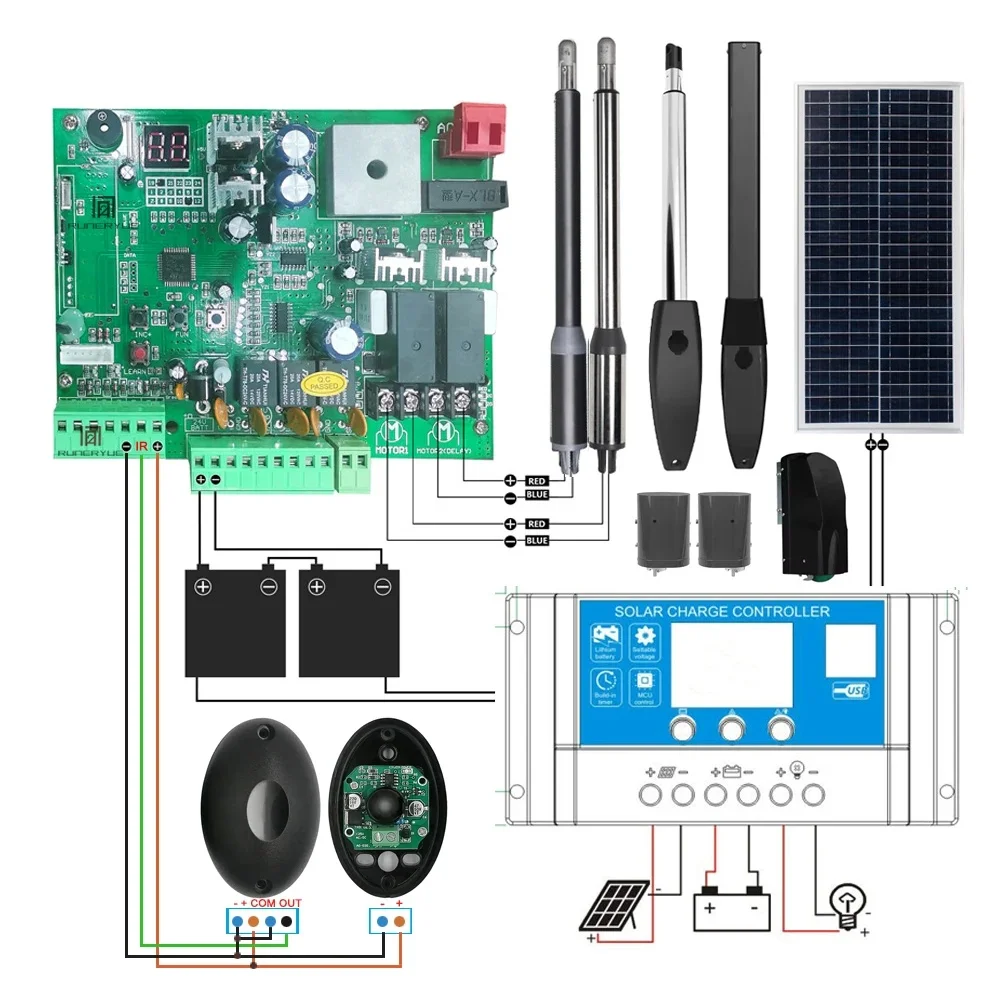
1. MOTOR 1: Master gate, close first & open last.This terminal connect 1st red wire(counted from your left hand side to right hand side)
2. MOTOR 2 (DELAY) : Slave gate, open first & close last.This terminal connect 1st blue wire (counted from your left hand side to right hand side).
NOTE! If you only have a single gate, the motor only can connect to the Motor 2 Delay terminal.
3. 2 SIDE: It is for connecting to any external device that operates a double gate.
4. COM: It is for connecting to the “ ground ”.
5. 1 SIDE: It is for connecting to any external device that operates the single gate.
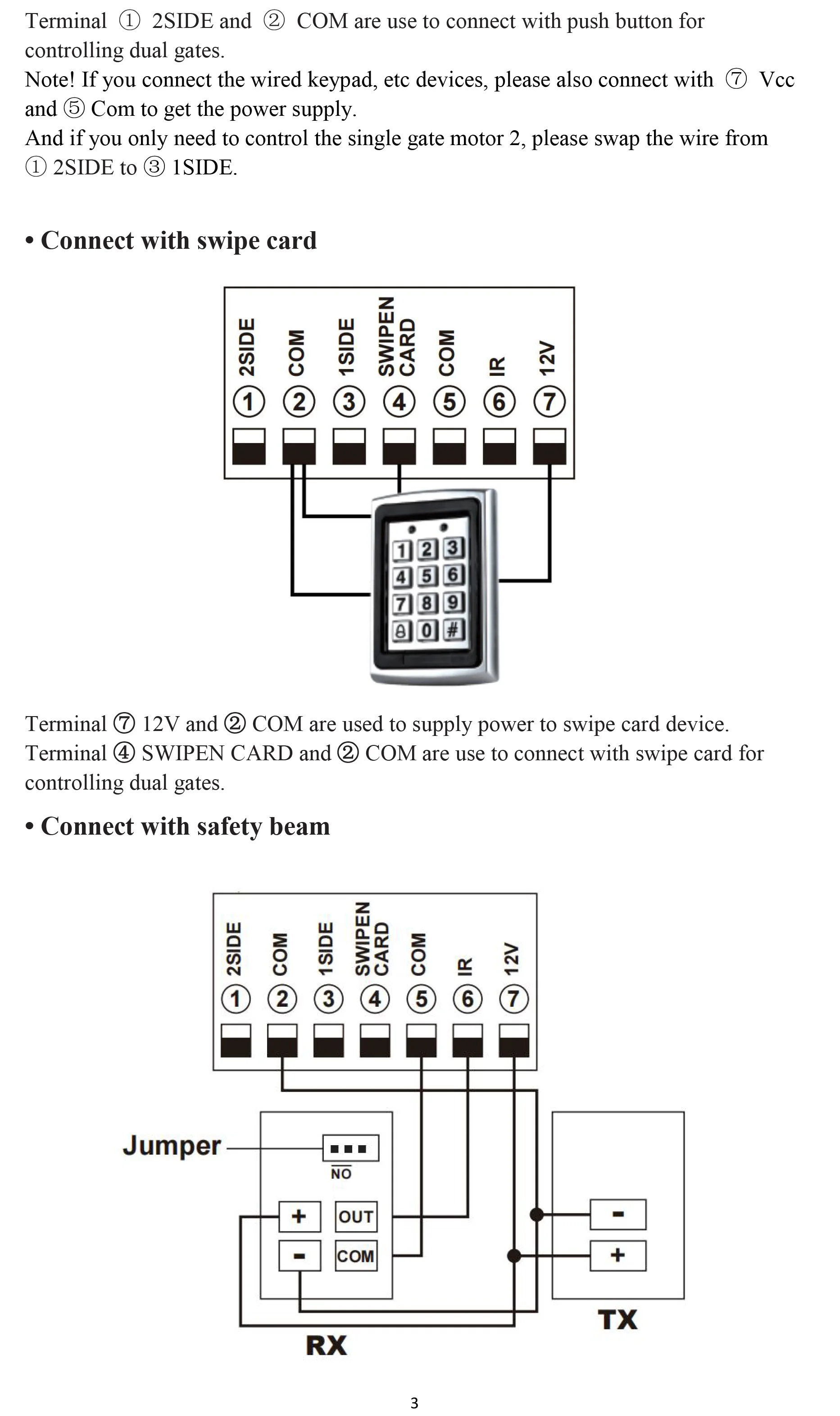
6. Swipe Card: It is for connecting to any external devices to open the gate.
7. COM: It is for connecting to the “ ground ” external device.
8. IR: Infrared terminal is for connecting to the safety beam.
9. 12V: The output is for connecting to the photocell sensor, continuous output current <=200mA. (24V DC output, current is 1A)
10. 24V battery +: It is for connecting the backup battery +.
11. 24V battery -: It is for connecting the backup battery -.
12. 24V: 24V DC output is for connecting to an external device. (such as photocell sensor, max current output 1A)
13. GND: It is for connecting to the “ ground ” of an external device.
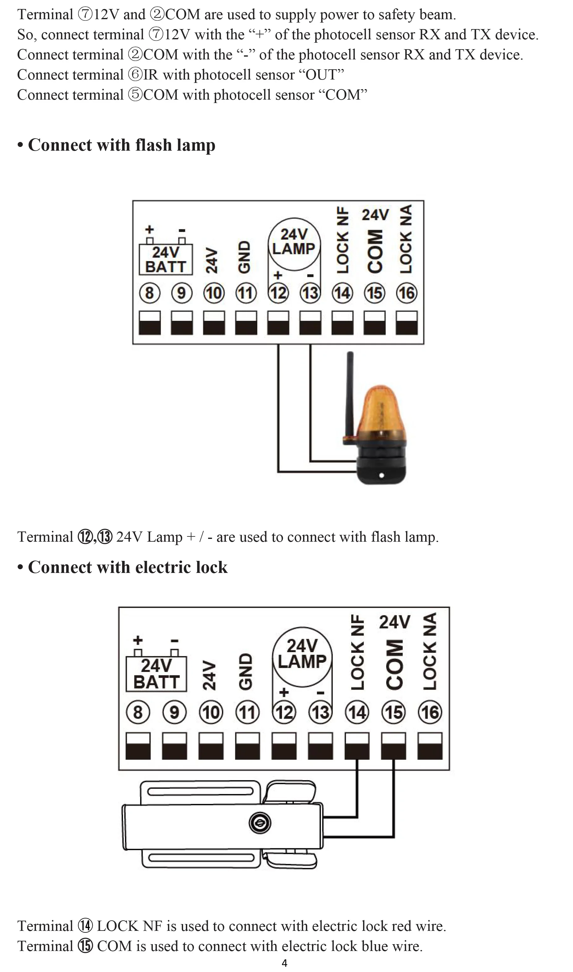
14. 24V LAMP +: It is for connecting to the flash light +.
15. 24V LAMP -: It is for connecting to the flash light -.
16. LOCK(NF): The NF terminal which used for connecting to the electric lock.
17. COM(24V): COMMON used for connecting to the“ground”of the lock.
18. LOCK(NA): The NA terminal which used for connecting to the magnetic lock.
19. GND: It is for connecting to the “ ground ” of the alarm system.
20. SP: It is 24V DC output connecting with the alarm system.
21. AC 24V: It is for connecting with the transformer.
22. Digital display: It is for showing you the setting data.
23. INC+: It is for figure increasing of setting the data.
24. FUN: Used for enter the menu setting and confirm the data.
25. DEC-: It is for figure decreasing of setting the data.
26. Learning button: It is for programming/erasing the remote control.
27. ANT and GND: used to connect with antenna.
Easy to use:
Button “1” is used to operate a single gate Motor 2; button “2” is used to operate a double gate for Motor 1 and Motor 2; button “3” is used to operate the alarm output.
Program new remote control:
1,Press the LEARN button on the control board for about 1 second, and the indicator LED will turn off, then means entering the programming.
2, Press any button on the new remote control for about 2 seconds. The digital display will show the remote's number while the board's indicator LED flashes four times with buzzer sound, which means the programming is successful.
Note! After you press the LEARN button, if the board does not receive the new remote signal within 5s, the indicator LED will turn on and exit programming.
3,Erase remote control:
Press and hold the LEARN button for about 5 seconds. If there has one buzzer sound and indicator LED light on, then now means removing the remote successfully.
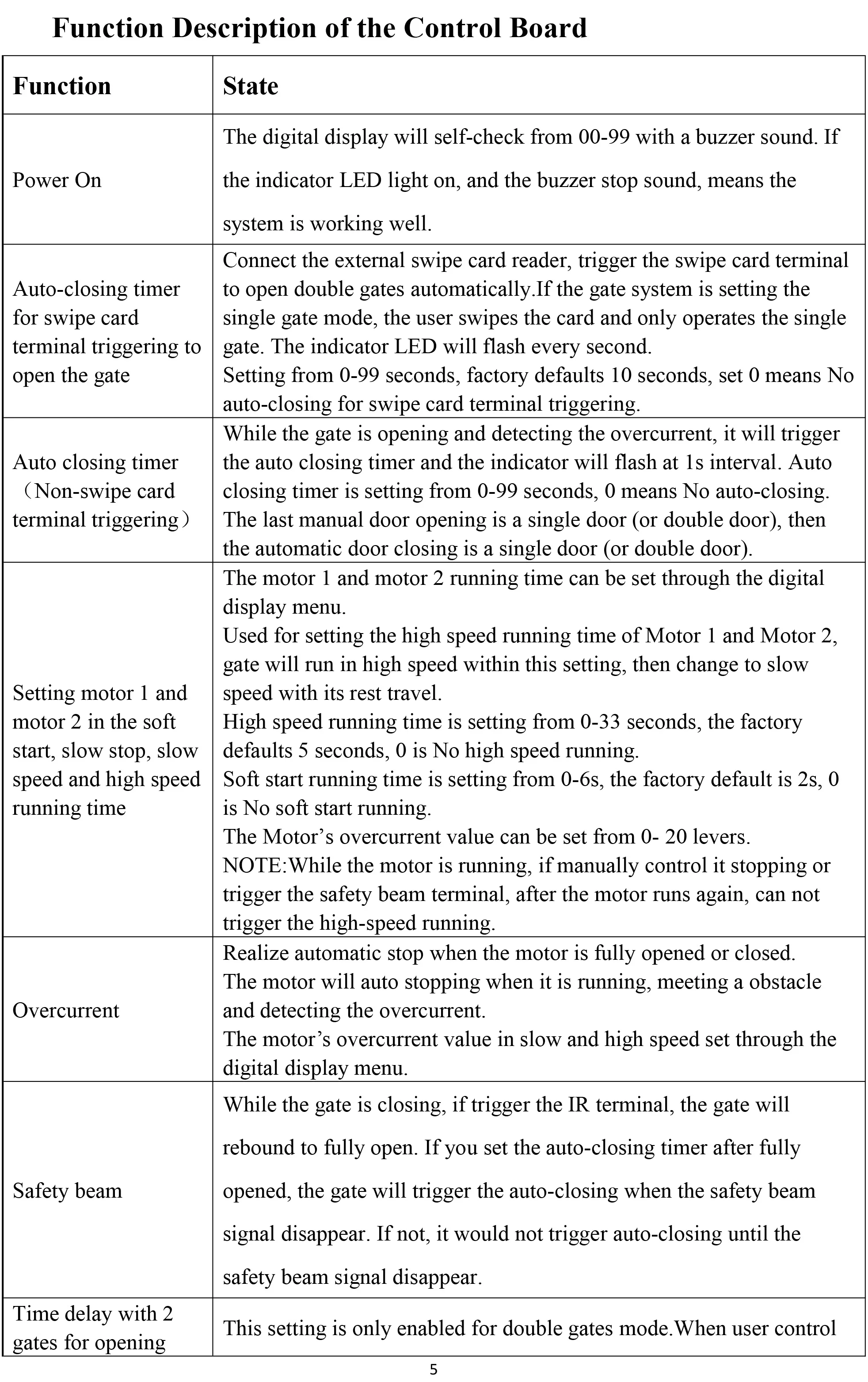
Function Description of the Control Board